Learning to Program – A Beginners Guide – Part Five – Running a program


In the last section, we looked at an imaginary computer architecture. In this section, we'll step through our first program from beginning to end, to see what it does. Then we'll actually run it on a computer!
We'll start out by investigating the program instruction memory.
Program instructions and the program counter
You can think of the program instructions like a list. The Control Unit keeps track of the current item by storing a value that references one of the items in that list (we sometimes say "points at" the item). We call that the Program Counter or Instruction Pointer.
Here's an example of a list of program instructions, and a program counter pointing at the 4th item in the list.
The program counter is usually implemented as one of those registers that we mentioned last time. Remember that a register is just a little bit of memory actually within the control unit. In this case, the number tells us the index of the current instruction in the list.
Zero-based indexing
This illustrates an interesting feature of most (but by no means all) computers and programming languages. When we number things, like items in a list or other sequence, we start numbering with 0, not 1. When our program counter is pointing at the 4th item in the list, it contains the value '3'.
So, if the first instruction is at location '0' should we call it the 'zeroth' item? The second instruction is at location '1', so should it really be called the 'first' item? Madness!
It is a bit easier to understand if, instead of thinking about it in terms of ordinals like 1st, 2nd, 3rd and so forth, you ask the question "what is the offset from the first item to the required item?" Then clearly the answer is '0' for the first item (you're there already), '1' for the second item (which is one after the start), and so on.
We often need to think about offsets like this, to reference one item in a list relative to another one.
For example, we could ask what the offset is from any arbitrary item in the instruction list to any other. If the current instruction is the one labelled "6" in the table above (JUMPLT 2), what is the offset to the one labelled "8" (LOAD R1 4)? Clearly, the answer is "2" (8-6 = 2)
You might also be thinking that the 2 in JUMPLT 2 has something to do with this offset of 2 between those two instructions? If so, you're already on the right lines - but we're skipping ahead a little.
Here's the program again, along with some of the other bits of the computer we described in the previous section.
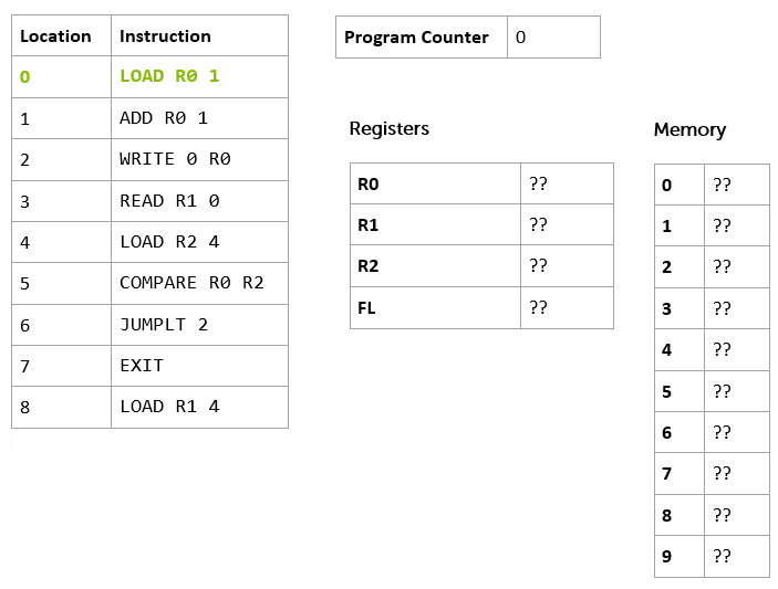
You can see our program instruction memory, with the program loaded, on the left, and the program counter, as before, this time pointing at instruction 0 (which I've highlighted in green and bold). We've added the other registers (remember that they are our 'local' storage on the processor itself) and the computer's memory - in this case 10 memory locations (0 to 9). A real computer might have a bit more memory than this!
Notice we've not got any external storage (like hard disks), output devices like screens and printers, or input devices like keyboards in our model computer yet. Just program instruction memory, data memory, some registers, and a program counter. We've also rather glossed over how the processor got started, and the program got loaded (a problem we call bootstrapping) - but we'll not worry too much about that for now.
Let's take look at the instructions themselves, starting at the beginning of the list.
LOAD R0 1
The first thing to say is that this instruction is one I've made up. In fact, I've made up this whole imaginary computer we're talking about. But most computers have an instruction like this in its architecture.
Here's the equivalent instruction for an Intel x86 processor:
MOV AH,1
And for the PowerPC
LI 0,1
And here it is for the venerable Zilog Z80 processor.
LD A,1
The first thing you'll notice is that this particular instruction comes in three parts. We call the first part the mnemonic and the remaining parts operands.
Processor
Mnemonic
Operand 1
Operand 2
endjin
LOAD
R0
1
x86
MOV
AH
1
PowerPC
LI
0
1
Z80
LD
A
1
The mnemonics are all very terse, but, as 'mnemonic' implies, they serve to remind you what the instruction is supposed to do.
A big barrier to learning to program is all the unpronounceable, abbreviated jargon. Don't worry: we're going to take some time to pull apart examples of these unpronounceable words whenever we come across them, and turn them back into English.
You'll also notice that all the mnemonics for this particular instruction are pretty similar - but legally distinct. There's a good reason for this; back in 1974, Intel asserted the copyright on their mnemonics, and so other processor manufacturers had to come up with their own, or get sued for copyright infringement! Some, though, were just ordinary words (like add) - so they couldn't be protected, allowing more or less everyone to use the same ones.
LOAD, LD and LI all indicate some kind of "loading" (at least, once you've seen LOAD and LD, you might recognize the L in LI as being related) and MOV might mean "move".
This mnemonic hints that the instruction is going to 'load' something into something else, or 'move' something from somewhere to somewhere else.
That's the mnemonic. The other two parts of this instruction are the operands. Looking at our instruction LOAD R0 1, the first operand R0 is the destination of the move/load. The second operand, the number 1, is the value to load.
You'll see this convention of destination first in a lot of programming instructions as we go along - even when we are dealing with quite high-level concepts like copying blocks of memory from one place to another, or managing lists, so it is worth getting used to it, even though we are probably more used to seeing "source" followed by "destination" in our left-to-right reading cultures. (Maybe this is more intuitive if you were brought up reading/writing Arabic!)
As you might have guessed from the name, the destination is one of the processor's registers. Register 0 (we're numbering things from zero again!) So, this instruction loads the number 1 into Register 0.
The equivalent instructions on other processors can be read in a similar way. It is helpful to know that the x86 version has a register called AH, the PowerPC just numbers its registers (from 0, of course!), and the Z80 has a register called A.
Once the instruction is executed, the control unit increments ("adds one to") the program counter, which now points at the next instruction.
Here's the state of the system once the first instruction has been executed.
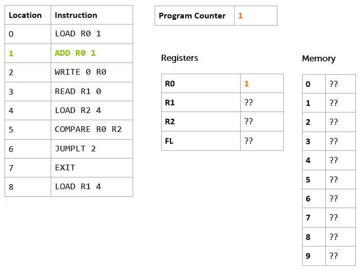
I've highlighted the changes in orange and bold. As you can see the program counter now holds the number 1, R0 also holds 1, and, as before, I've highlighted the next instruction to be executed in bold green:
ADD R0 1.
Let's try and deconstruct this one.
Mnemonic
Operand 1
Operand 2
ADD
R0
1
The mnemonic ADD indicates that we might be adding things up. Our destination first convention (remember, that's just a convention, not any kind of hard-and-fast rule) suggests that the result might end up in R0, and the 1 is probably one of the two values to add. Given that there are only 2 operands in the instruction (R0 and 1) it is probably safe to assume that R0 is part of the addition too.
So, in our programming language ADD R0 1 means "add 1 to the value of R0 and put the result in R0".
As before, other (real!) processors have similar instructions.
x86
PowerPC
Z80
ADD AH, 1
ADDI 0,0,1
ADD A, 1
Notice that the PowerPC instruction is slightly different from the others - it has three operands after the mnemonic.
Mnemonic
Operand 1
Operand 2
Operand 3
ADDI
0
0
1
The first is, as usual, the destination of the add operation, but you can then separately specify the two values to be added together (a source register and a value). Not all processors are exactly the same!
So, what does the system state look like when we've finished this operation?
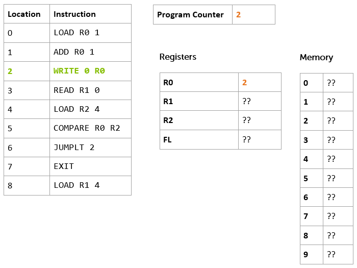
Hopefully, you worked out that the program counter would now point at offset 2, and R0 would contain the value 2.
On with the next instruction: WRITE 0 R0. This is the first time we see an instruction that deals with the Data Memory.
We should be getting used to decomposing these into mnemonic and operand by now.
Mnemonic
Operand 1
Operand 2
WRITE
0
R0
The mnemonic WRITE implies that we are writing something somewhere, and our destination-first convention implies that we are writing to 0. In this case, we interpret the value of the operand as 'the Data Memory location at offset 0'. The other operand tells us what we are writing - the value stored in R0.
Our representative battery of real processors have a variety of different ways of representing this kind of "write to memory" instruction, and it is worth taking a look at them.
x86
PowerPC
Z80
MOV BYTE PTR [0], AH
STB 0, 0(0)
LD (0), A
The Intel x86 version looks quite odd, but it is actually being pretty explicit about what it is intended to do. It uses the MOV mnemonic we've already seen to tell us we're moving a BYTE of information (more on that later) into memory location at offset 0, from the value stored in the AH register. Notice how it uses square brackets round the memory location, and the mnemonic PTR to indicate that the value is "pointing" at a particular memory location.
The Z80 version is like a simpler version of the x86 instruction. It reuses the same LD mnemonic we've already seen, and makes use of parentheses to indicate that we're addressing memory (just like the x86 MOV instruction, but round brackets this time instead of square, and without the BYTE PTR stuff). On our usual destination-first basis, we can read LD (0), A as "store the contents of register A in the memory location at offset 0".
The PowerPC version is actually the 'oddest' of the three. You don't need to read the gory details of this bit unless you're really interested in the PowerPC architecture, but it is Quite Interesting.
(Still reading? Good.)
First, it flouts the "destination first" convention, in that the first operand is the register whose value is to be written to memory. The second operand is made up from two parts we'll call D and (RA).
In this case the operand is 0(0) so, D=0, and (RA)=0.
The (RA) part specifies the number of a register. The control unit takes the value in the specified register, adds it to the value of D and uses that as the memory location to which to write the value.
So if R1 contained the value 4, the instruction STB 4, 3(1) would mean "write the value stored in register R4 to memory location at offset 7" (which is 3 + the value of R1, i.e. 3 + 4).
However, if the value of RA is 0, then it is a special case. It doesn't take the value of R0, it just uses the value of D alone. So, STB 0, 0(0) means "write the value stored in register R0 to the memory location at offset 0".
Spot test:
If R0 contains 3, R1 contains 4 and R2 contains 5
What does STB 2, 3(0) mean?
What about STB 1 5(2)?
Answer:
STB 2, 3(0) means "write 2 to the memory location at offset 3".
STB 1 5(2) means "write 4 to the memory location at offset 10".
Did you get that? If so, this is one of those small moments of triumph I was talking about in the introduction. If not, go back and re-read the previous couple of paragraphs, and see if you can work it out again. Once you've enjoyed the moment of triumph, read on…
(If you skipped the gory details of the PowerPC instruction, now's the time to re-join us. You missed a moment of triumph, too, so you might want to go back and read it anyway.)
Even if you skipped the PowerPC stuff, that seemed like a pretty epic amount of detail for what seemed like such a simple instruction!
Why might that be so?
The previous instructions we've looked at just worked with a specific register, which we refer to by name, so they were very simple. Instructions that refer to the data memory need to specify first that they are talking about the data memory, and then the offset into that memory, and so are a little bit more complicated.
But let's remind ourselves that in everyday use, it isn't really all that complicated
Here's our instruction again:
WRITE 0 R0
And it writes the value stored in register R0 to the memory location at offset 0.
So, what is the state of the system now we've executed that instruction?
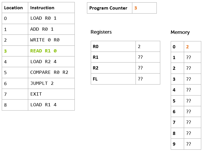
The register R0 contained the value 2 at the outset (and still does at the end!). But now, the memory location at offset 0 contains the value 2. The program counter has advanced one again, and now contains the value 3, which points at the instruction at offset 3.
We're ready for the next instruction:
READ R1 0
Given the mnemonic READ, our usual destination-first convention, and what we already know about WRITE, it should be fairly easy to guess what this does. Points to you if you've just thought "store the value found in the memory location at offset zero in register R1".
Here are similar instructions on the usual array of example processors.
x86
PowerPC
Z80
MOV AL, BYTE PTR [0]
LBZ 0, 0(0)
LD B, (0)
Hopefully, you're getting the hang of reading all these different instructions by now. In fact, you're starting to get proficient at the basics of 4 different programming languages! Most developers only ever get around to learning 2 or 3 languages in their lifetime, so you're off to a good start.
Another spot test:
Given that R3 contains the value 1 and R1 contains the value 5, what does LBZ 4, 3(1) mean on PowerPC?
How about MOV AL, BYTE PTR [4] on x86?
If you said "store the value found in the memory location at offset 8 - that's 3 + the value stored in R1, which is 5 - in the register R4" then that's one point for the first question.
If you said "store the value found in the memory location at offset 4 in the register AL" for the second question, you'd be right again, and you're really getting the hang of this.
So, once we've executed this instruction, here's the state of the system again.
The program counter has advanced again, and now refers to the instruction at offset 4. R1 contains the value 2 (which corresponds the value in the memory location at offset 0).
So, this is the next instruction.
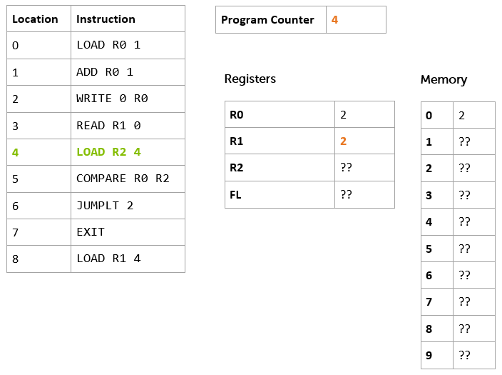
LOAD R2 4
You should be able to do this one yourself, as we've seen an example before.
If you said "stores the value 4 in the register R2", you're right again. If not, then go back and have a quick look at the description of the very first instruction to refresh your memory.
As a general point, don't worry if you get any of these questions wrong the first time - or the second time, or the third time. Just take a break, then re-read the relevant bit, and see if you can sort it out for yourself. When it clicks, then you can move on. It doesn't matter how long it takes, as long as you get there in the end; try not to skip ahead, though, until you've understood the current section.
Now, what about the equivalent instructions for x86, PowerPC and Z80? What do you think they're going to be?
To work it out, you're going to need to know another register name on each platform.
For PowerPC we can use R2. (In real life, we might not actually use R2, as registers often have special purposes by convention, but for now we can ignore this constraint). On the Z80 let's use a register called C. And on x86 we'll use CH.
You can refer back to the beginning of this section to remind yourself of the syntax for a "store a value in a register" instruction, if you need to.
Here are the answers:
x86
PowerPC
Z80
MOV CH, 4
LI 2, 4
LD C, 4
How did you do? If you got all that right, then the small moments of triumph are coming along thick-and-fast. If not, read it all through again until you've got it.
Finally, what's the state of the system going to be now we've executed this instruction? Work it out for yourself, before you look at the diagram below.
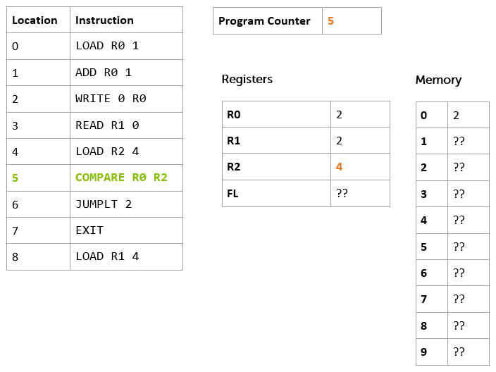
OK, the program moves remorselessly on with the next instruction.
COMPARE R0 R2
So far, most of the instructions we've seen have been storing values somewhere - in data memory or registers. This one has more in common with the ADD instruction, in that it performs some kind of operation on two values, and stores a result somewhere. These are the kinds of instructions traditionally executed by the ALU (which you may remember from our architecture diagram in the previous section).
It should be obvious that this one 'compares' two values. Specifically it works out if the value stored in R2 is greater than the value stored in R0, less than the value in R0, or the same as the value in R0. It then stores this result somewhere. But where?
In our example computer, there's a special register called FL (we'll discuss why it is called that later) and the COMPARE instruction stores the result in there. The value it stores depends on the result of the comparison.
Result
FL
R0 = R2
0
R0 < R2
1
R0 > R2
2
What about the other processors?
x86
PowerPC
Z80
CMP AH, CH
CMP 0, 2
CP C
In this case, x86 and PowerPC are very similar, and the Z80 is the odd-one out in that its CP instruction only seems to have one operand. This is because on the Z80 you can only ever compare to the A register (which it calls the 'accumulator'), so you don't need a second operand. It has other special instructions to perform the kinds of tasks for which you might use a compare instruction on other platforms.
OK, so what's the state of our computer now? See if you can work it out, then look at the diagram below.
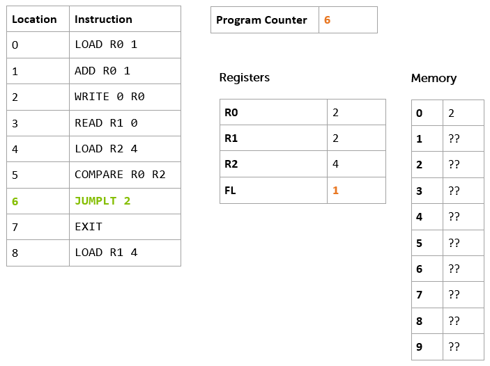
Is that what you expected? Here's how you should have worked it out. If we look back at our registers, R0 stores the value 2 and R2 the value 4. Basic maths tells us that 2 < 4, and if we look in our comparison table above, we see that FL should be set to the value 1.
The program counter has incremented again… On with the next instruction.
JUMPLT 2
This is another new type of instruction. We've seen load and store instructions (LOAD, READ, WRITE), arithmetic and logical instructions (ADD, COMPARE) and now we've got a flow control instruction. Flow control is all about changing which instruction we're going to execute next.
So, the JUMP part of the mnemonic tells us we're going to change the value in the program counter, and the operand tells us how far we're going to jump - in this case, 2 instructions ahead.
The LT part of the mnemonic is a condition on the jump. We're only going to perform the jump if the FL register contains a value which indicates that the last comparison came out as a "less than" result (i.e. FL contains 1)
Reading all that in one go, JUMPLT 2 means "jump ahead two instructions if the result of the last comparison was that the value of the first operand is less than value of the second operand"
There are, of course, similar instructions on the real processors.
x86
PowerPC
Z80
JL 2
BC 0, 0, 2
JR C,2
The x86 instruction is fairly self-explanatory. JL means "jump if less than" and the operand is the relative offset.
The Z80 instruction isn't quite so obvious - it means "make a relative jump 2 instructions forward, if the 'carry flag' is set", which, it turns out, means the same as our JUMPLT instruction. We'll find out why later on, but it is to do with how we represent numbers in the computer.
The PowerPC instruction looks even more confusing. The mnemonic BC means "branch conditionally". The first operand gives the processor a hint about what you think the outcome of the condition might be. By passing 0, we've told it that we have no idea. The second operand specifies the condition we want to check. By passing 0, we're telling it that we want to check the "Less Than" condition. The third operand is, as you might have guessed, the offset for the branch.
So, what happens when we execute this instruction? See if you can work out the state before you look at the diagram below.
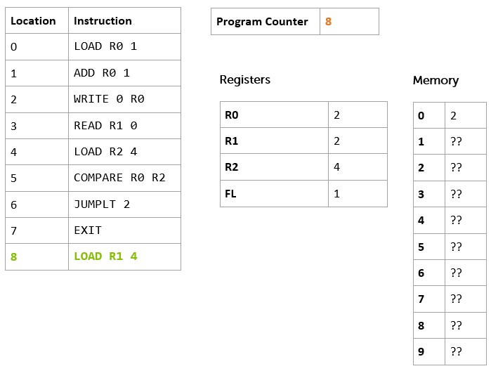
Did you work it out? Here's the reasoning: The FL register contains the value 1 which means that the outcome of the last comparison operation was "less than". The control unit therefore added the offset to the program counter, and so we resume execution at position 8, skipping our EXIT instruction (which would have ended program execution).
So, our final instruction is ready to be executed: LOAD R1 4. You should be able to work this one out, too, as we've seen a LOAD instruction a couple of times before. Here's the final state.
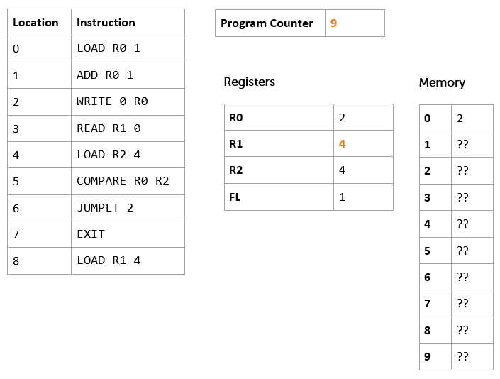
OK, so the program counter now reads 9… what's going to happen next? That rather depends. The control unit is now supposed to read the instruction at offset 9. This doesn't sound good, because there doesn't seem to be any such instruction. On some processors it would read the next instruction in program memory - that could be pretty much anything; something left over from the last program we loaded, if it was longer than the current one, or maybe some "default" instruction, or something completely random that might not make sense!
Our computer helps us to not shoot ourselves in the foot like this, detects that we have run off the end of our program instructions, and just stops working, with an error.
Let's amend our program so that it exits tidily.
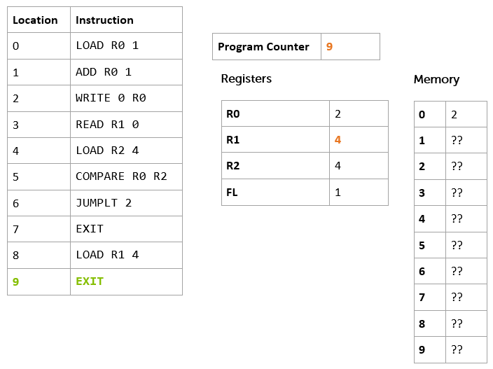
We've added an extra instruction to the end - EXIT - which terminates the program neatly. This time, when we run to the point where we've executed the instruction at offset 8, the program counter contains the value 9, and the instruction at offset 9 is ready to be executed. Here's the final state.
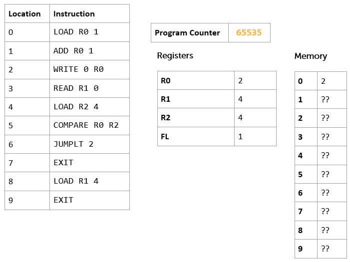
You'll notice that the control unit has decided to store the value 65535 in the program counter to indicate that we're done. We'll look at why that might be in a later section.
So, we've finished executing our first program (albeit on paper), and learned a whole bunch of different instructions on 4 different processors. The actual set of instructions on any particular processor can be completely different (and some processors have way more instructions than others), but they all support at least a basic set of the same kinds of operations.
In the next section, we're going to look at how values are stored in our computer in more detail.
First though, let's recap on what we've just learned, to get it straight, and then try a few exercises (including actually running our code on a computer!)
Recap
In this kind of computer architecture "running a program" means taking the instruction at the offset specified by the value stored in the program counter and executing it. Once it has executed, the control unit ensures that the value stored in the program counter is increased by one, ready to go on, until the program is terminated.
The instructions we've seen fall into three broad categories:
1. load and store instructions, which can read values from and write values to registers (a small number of individual storage locations on the processor itself) and the data memory. We've seen the examples LOAD, READ and WRITE
2. arithmetic and logical instructions, which can carry out mathematical and logical operations on the values in registers (and, sometimes, data memory). We've seen the examples ADD and COMPARE
3. flow control instructions, which cause the control unit to change the value in the program counter, sometimes on the basis of a condition. We used the JUMPLT example to skip over an instruction based on the result of a previous comparison.
An instruction consists of a mnemonic which indicates what the instruction is going to do, and, optionally, one or more operands which define the information that the instruction is going to operate on. We learned about the destination-first convention for operands (and saw how it isn't a hard and fast rule).
We've also seen examples of how to specify constant values, the value stored in a register, or the value stored in the memory location at a particular offset.
And we've looked at the different approaches taken by some popular processors for these common instructions, as well as our example "computer".
If you've got that all in your head, you're ready to go on to the exercises.
Exercises
In this section you're going to write your own first program, and actually run it; not just "on paper" but on a computer.
First, make sure you've set everything up according to the instructions in the Getting Started section. Then, download the file computer.fs from Endjin's sample repository (right click that link and choose to save the target to your computer). Then, open it up in your favourite text editor (this one is good).
Let's take a look at it, line by line.
The first line just says that we are in a module called Endjin.Computer
module Endjin.Computer
Then, there's an interesting block:
You should recognize this as the program from the previous section. Notice that each instruction is wrapped in quote marks (e.g. "load r0 1").
We've also written the instructions all in lower-case. As it happens, this computer doesn't care whether you write your instructions lower case, upper case, or a mixture (most do care, but we're being especially forgiving.)
The rest of the file contains the code that makes this 'computer' work. We won't look at that now. Instead, let's actually run our program.
To do that, we're going to use the F# environment we set up in our Getting Started section.
So, as you did when we tested our install, you should start up a command prompt (Windows) or Terminal (Linux), and change directory to the one in which you saved computer.fs.
Then, use the F# interactive environment to run the program.
Linux/MacOSX:
fsharpi computer.fs
Windows:
fsi computer.fs
If all is well, you'll see a load of output scroll by.
It starts with the standard F# version information and copyright statement.
On Windows, it will look something like this
Microsoft (R) F# Interactive version 11.0.60315.1
Copyright (c) Microsoft Corporation. All Rights Reserved.
And on Linux/MacOSX, it will say
F# Interactive for F# 3.0 (Open Source Edition)
Freely distributed under the Apache 2.0 Open Source License
It suggests how you might get help
For help type #help;;
And then tells us that it is loading the file. This will vary, depending on where you saved your file (mine was on my Windows desktop)
[Loading C:\Users\Matthew\Desktop\computer.fs]
Then, it starts to show us the output of running the program:
load r0 1
R0=1 R1=0 R2=0, WR0=0, WR1=0, WR2=0, PC=1, FL=0
0 0 0 0 0 0 0 0 0 0
Each block shows the instruction that has been executed, followed by the values stored in each of the registers, the program counter (PC) and the special FL register. The last line gives us the value stored in the data memory at each offset (the value at offset zero is the left most number, and so on).
You should be able to follow through all the output of the program along with the discussion in the previous section
load r0 1
R0=1 R1=0 R2=0, WR0=0, WR1=0, WR2=0, PC=1, FL=0
0 0 0 0 0 0 0 0 0 0
add r0 1
R0=2 R1=0 R2=0, WR0=0, WR1=0, WR2=0, PC=2, FL=0
0 0 0 0 0 0 0 0 0 0
write 0 r0
R0=2 R1=0 R2=0, WR0=0, WR1=0, WR2=0, PC=3, FL=0
2 0 0 0 0 0 0 0 0 0
read r1 0
R0=2 R1=2 R2=0, WR0=0, WR1=0, WR2=0, PC=4, FL=0
2 0 0 0 0 0 0 0 0 0
load r2 4
R0=2 R1=2 R2=4, WR0=0, WR1=0, WR2=0, PC=5, FL=0
2 0 0 0 0 0 0 0 0 0
compare r0 r2
R0=2 R1=2 R2=4, WR0=0, WR1=0, WR2=0, PC=6, FL=1
2 0 0 0 0 0 0 0 0 0
jumplt 2
R0=2 R1=2 R2=4, WR0=0, WR1=0, WR2=0, PC=8, FL=1
2 0 0 0 0 0 0 0 0 0
load r1 4
R0=2 R1=4 R2=4, WR0=0, WR1=0, WR2=0, PC=9, FL=1
2 0 0 0 0 0 0 0 0 0
exit
R0=2 R1=4 R2=4, WR0=0, WR1=0, WR2=0, PC=65535, FL=1
2 0 0 0 0 0 0 0 0 0
Completed successfully
Finally, we get to some output from the F# runtime. We can ignore this for the time being - we'll discuss what it means in a later section.
As we're done, we can quit the F# runtime by typing
#quit;;
That's quite a step forward - we've run our first program.
Now, let's see what happens if we modify that program. I could add an extra instruction to the program, for example.
Say I want to subtract 2 from r0 just before the end. There's an instruction to do that - SUB R0 2 that works in a very similar way to ADD.
Let's add it in to the program.
If we save the file, we can run it again:
Linux/MacOSX:
fsharpi computer.fs
Windows:
fsi computer.fs
We see the following output:
load r0 1
R0=1 R1=0 R2=0, WR0=0, WR1=0, WR2=0, PC=1, FL=0
0 0 0 0 0 0 0 0 0 0
add r0 1
R0=2 R1=0 R2=0, WR0=0, WR1=0, WR2=0, PC=2, FL=0
0 0 0 0 0 0 0 0 0 0
write 0 r0
R0=2 R1=0 R2=0, WR0=0, WR1=0, WR2=0, PC=3, FL=0
2 0 0 0 0 0 0 0 0 0
read r1 0
R0=2 R1=2 R2=0, WR0=0, WR1=0, WR2=0, PC=4, FL=0
2 0 0 0 0 0 0 0 0 0
load r2 4
R0=2 R1=2 R2=4, WR0=0, WR1=0, WR2=0, PC=5, FL=0
2 0 0 0 0 0 0 0 0 0
compare r0 r2
R0=2 R1=2 R2=4, WR0=0, WR1=0, WR2=0, PC=6, FL=1
2 0 0 0 0 0 0 0 0 0
jumplt 2
R0=2 R1=2 R2=4, WR0=0, WR1=0, WR2=0, PC=8, FL=1
2 0 0 0 0 0 0 0 0 0
load r1 4
R0=2 R1=4 R2=4, WR0=0, WR1=0, WR2=0, PC=9, FL=1
2 0 0 0 0 0 0 0 0 0
sub r0 2
R0=0 R1=4 R2=4, WR0=0, WR1=0, WR2=0, PC=10, FL=1
2 0 0 0 0 0 0 0 0 0
exit
R0=0 R1=4 R2=4, WR0=0, WR1=0, WR2=0, PC=65535, FL=1
2 0 0 0 0 0 0 0 0 0
Completed successfully
I've highlighted the differences from the previous run. You should see that it executes the sub instruction, and the value of r0 is updated appropriately.
If that all worked, we're ready to try our first substantial exercise.
Exercise 1
- Write a program to add up the integers from 1 to 10, and put the result in to the memory location at offset zero.
(To check your answer, SUM{1...10} = 55)
- Now, alter the program to add up the integers from 1 to 15 and put the result in to the memory location at offset zero.
(Again, to check your answer, SUM{1...15} = 120)
- Now, alter the program again, to add up the numbers from 5 to 15, and put the result into the memory location at offset zero.
(Again, to check your answer, SUM{5...15} = 110)
(We'll discuss some possible answers in the next section.)